Car Differential
September 2021 – December 2021
Overview
For my mechanical design class, our big goal was to take everything we’d learned throughout the semester and actually build (well… design) a real mechanical system. As a car enthusiast, I pitched the idea of designing a rear differential, and my group was onboard immediately. A differential is one of those things that seems simple until you actually try to design one from scratch… then you realize it’s a surprisingly complicated little box of gears.
To avoid picking completely random loads, we based our design on something real: a 2021 BMW M3. That gave us actual torque numbers, wheel speeds, gear ratios, etc., so we weren’t just inventing fake values. After running the math for the input and output shafts, we got a good idea of the torque the diff would need to handle.
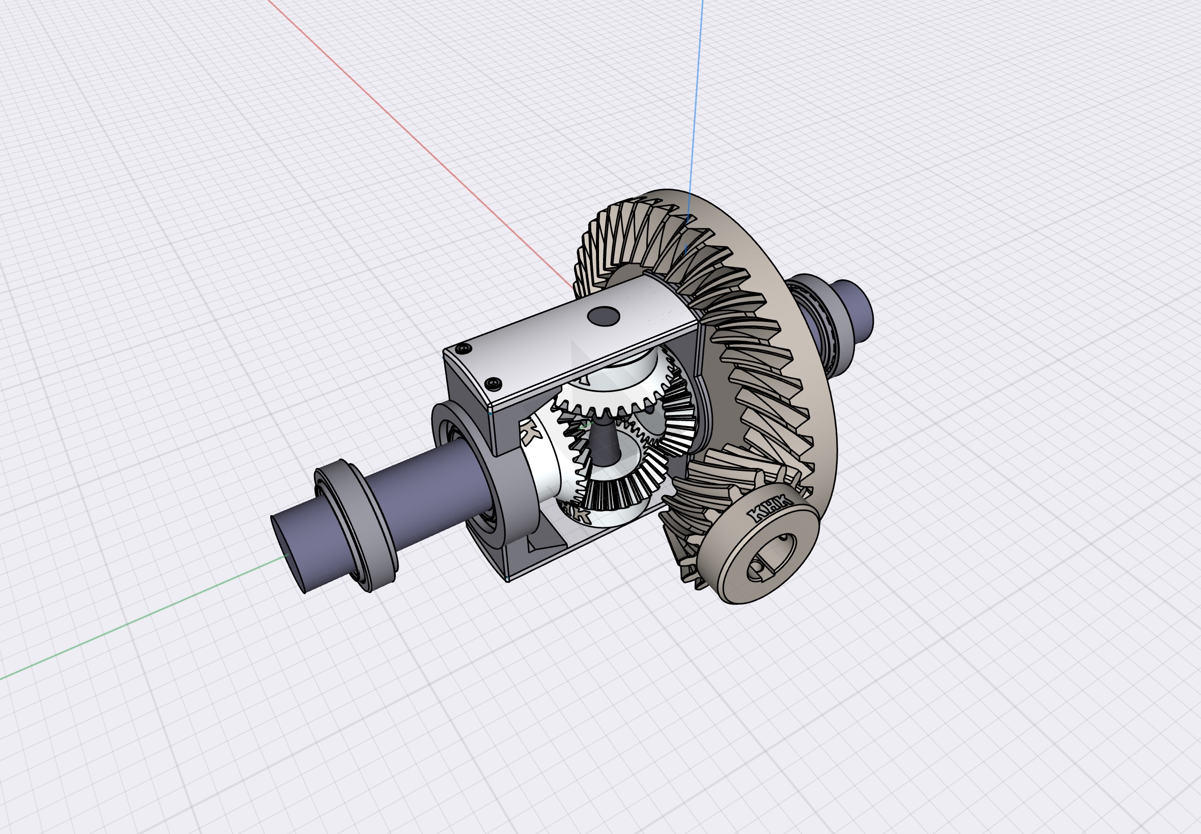
From there, we started hunting for real, off-the-shelf gears and bearings that fit the loads. Once we settled on a set of bevel gears, miter gears, roller bearings, and some 1045 steel for the shafts and housing, I modeled everything in Shapr3D to build the full differential assembly.
We conducted a detailed analysis of three critical components using AGMA gear-design equations and classical fatigue methods, including the RR Moore endurance limit for rotating shafts. The components reviewed were the crown gear, one of the output shafts, and a tapered roller bearing. The shaft and bearing both met their required performance criteria with comfortable safety margins — the bearing, in particular, offered a service life far exceeding project needs. The crown gear, however, did not. When evaluated using AGMA bending and contact stress equations, the calculated gear-tooth stresses surpassed the allowable limits, indicating the gear would not endure the expected loads. In practical terms, the design required a revised gear selection better aligned with the application’s torque and fatigue requirements. This is a typical part of real engineering work: the analysis guides the design, and the design iterates until the numbers and the hardware are in agreement.
Even though the first iteration of the design wasn’t strong enough, this project was super valuable. I got hands-on practice selecting real parts from suppliers, doing full mechanical analysis, and building a clean CAD assembly. It was also a good reminder not to assume that “the biggest gear we find on Google will definitely survive 900+ lb-ft of torque at 3,000 rpm.” Turns out… not always.
Overall, this project combined everything: load estimation, part selection, redesign, failure analysis, and a lot of CAD time. And honestly, even though the differential didn’t survive the math, the process taught me way more than a perfect design ever would. The write up for this project is attached below.
Attachments
Technologies & Tools
Gallery


