Machining of Model Lightsaber Hilt
September 2021 – December 2021
Overview
This project was for my machining class, where the whole point was to prove that we could actually manufacture something using the machine shop — not just model it on a computer. A lot of engineering school is designing things you never actually touch, so being able to physically build the thing I designed was what made this project awesome.
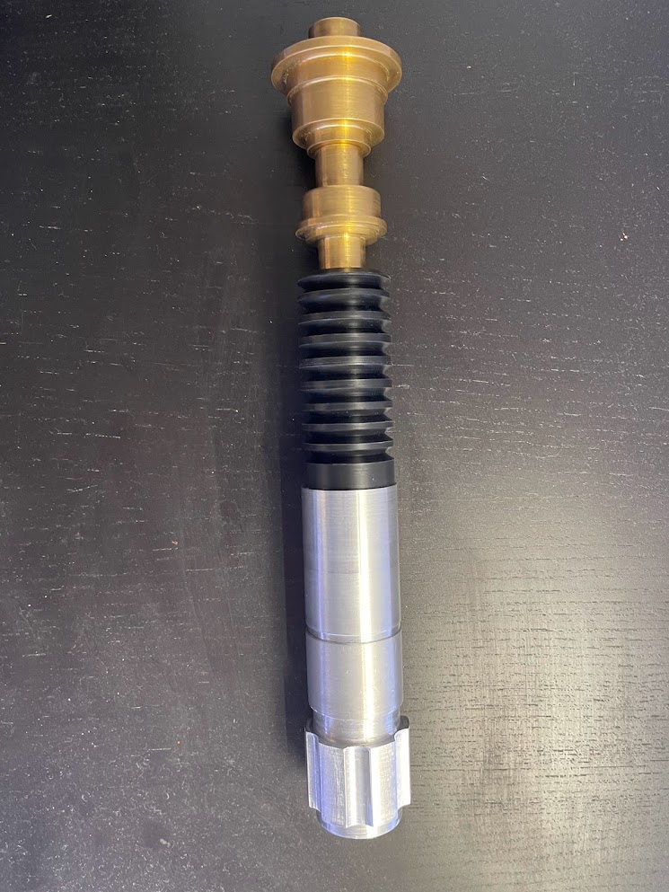
As a huge Star Wars fan (seriously, I know way too much about that franchise), I decided it would be fun to machine a lightsaber hilt. I found a schematic of Obi-Wan Kenobi’s hilt — probably my favorite design — and used it as the foundation. To meet the project requirements, we needed to use a bunch of different machining operations, so we split the hilt into multiple sections made from different materials, all threaded onto an internal rod.
I modeled everything in Shapr3D, then we headed into the shop.
Brass Sections (Top + Bottom):
We bandsawed two pieces of brass stock, then turned them on the lathe to get the profile right. The shop staff walked us through the proper feed rates and spindle speeds — brass ran nicely at higher RPM without deforming. After turning, we drilled the centers and tapped the threads that would connect to the internal rod. Both parts started to look like real lightsaber components pretty quickly.
Delrin Grip Section:
The grip needed a black finish, so the shop guys recommended Delrin. This was bandsawed to size, then turned at a much slower 185 RPM (compared to ~340 RPM for the brass). Brass can take heat without noticeable deformation, but Delrin will absolutely melt if you run it too fast. We cut the grooves manually on the lathe using the digital readout to get spacing right.
Aluminum Sections:
The bottom two sections were made from aluminum. We bandsawed them to length and turned them down on the lathe. The upper aluminum piece only needed turning, but the lower pommel section required us to mill six evenly spaced vertical grooves. Up to this point, everything had been machined manually, but for the grooves we used the CNC mill and programmed it to do the spacing automatically — way cleaner than trying to eyeball it.
Internal Rod:
The last piece was the internal connector rod. We cut down a ½-inch aluminum rod, faced it, and then programmed the lathe to cut a 1/2"-13 thread onto both ends. All the external parts were drilled with ½-inch holes so they could slide onto the rod… at least that was the plan. When we went to assemble everything, nothing fit. The holes were too tight, and the threads didn’t mate cleanly. Classic tolerancing lessons.
So, we went back, widened the holes slightly, and ran the threading program a few more times. After a lot of trial and error — and a lot of test-fitting — everything finally slid together and threaded properly.
And just like that, we had built a lightsaber.
There’s a full write-up of the project attached below, but honestly, the hands-on experience was the real win here. Getting to take a design from CAD to a physical, fully machined object was one of the most satisfying projects I’ve done.
Attachments
Technologies & Tools
Gallery


